This weekly debrief is for paying supporters of my work. Please only read if you’ve paid. Thanks!
→ Click here if you've paid ←
Exams are over and I’m free until January, which means that it’s time to get things done. The November Turbothon has begun.
bedrock-micro
The Bedrock hardware projects have languished while I’ve been locked in for the semester, I’ve only been able to find a bit of time here and there to work away at the updated specification (which has also been slow going). Now that I’ve completed my exams I’ve finally got the time to sprawl out and work on my own projects. I’m so hyped, it’s been a long time coming.
My big goal is to have a working prototype of the bedrock-micro board by the end of the year, along with a couple of separate device boards. There’s lots to get done here, the biggest of which is definitely going to be learning how to design and order printed circuit boards. I’ve used perf board / vero board with prototyping wire in the past, but that’s not going to cut it for these bigger projects. Especially when lots of parts only come in surface-mount packages, not through-hole (and even when through-hole is available, it’s more expensive).
Two boards
I keep changing up the plans for bedrock-micro as I figure things out, but I’ve got it pretty much locked down now. I’m going to make two different board designs, one fancier than the other.
The first board design will provide the core system with 64KB of program memory and at least 128 bytes for each stack, and will have a microSD card reader for the file device and a row of GPIO pins for the GPIO and input devices. It’ll be built around an ATmega328P microcontroller, the same as what’s used in the Arduino Nano (the first one at least, there’s like a thousand different variants these days). It’s cheap, it’s efficient, it’s relatively simple, it’s familiar to a lot of people, and it’s available in huge quantities for a price of around NZD$3.40 (surface-mount). This board is going to be mostly through-hole though, the intention is that I should be able to send people a PCB and a handful of parts and they can solder up their own computer. The system will implement the system, math, clock (kinda), input, file, clipboard, and registry devices. The tone and waveform devices should be possible too, but I’ve only got so much time for now.
The second board will be the same as the first, but will add on a 128 by 64 pixel LCD screen, another 64KB memory chip, and some built-in controller buttons. This one is going to be all surface-mount and as small as possible. The extra memory chip will support the memory device and the screen device. I plan to use the exact same firmware for both boards.
What I’ve done so far
This past week has been spent figuring out how to program these microcontrollers and getting a nice workflow set up.
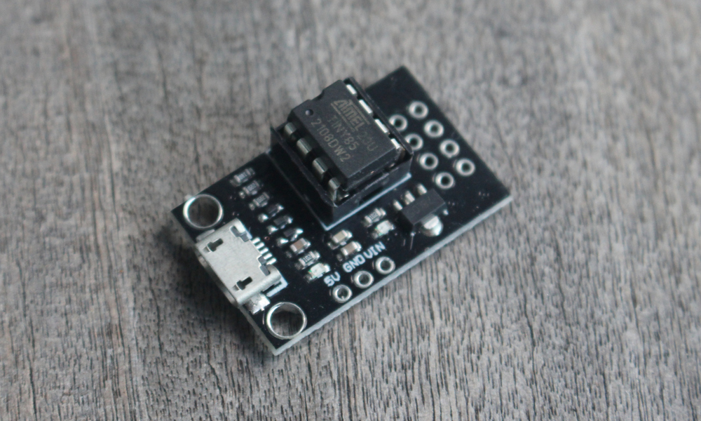
I started with the ATtiny85 chip, which is like a tiny version of the ‘328 that I’ll be using for the main system. I bought it on a whim a year ago for around NZD$4, it came with a tiny programming board with a microUSB connector for connecting to a computer.
I’d only written firmware for the 8-bit PIC series of microcontrollers before, which are all exceedingly simple and cheap and efficient, but to balance the scales they’re burdened with possibly the worst official developer experience I’ve ever seen in my life. You have to boot into Windows to use a hulking prehistoric IDE to write assembler code that can only be assembled from the inside of a C file, and then the assembled hex is flashed to the chip using a proprietary programmer board. I never actually succeeded completely in getting the assembler code assembling, there’s zero documentation for how to do it and it’s clear that the company is reluctant with supporting assembly programming in the first place — they’d much rather you wrote everything in C.
Learning about AVR microcontrollers
In comparison, the AVR chips (ATtiny, ATmega) are a dream to work with. That developer board turned out to be a bit of a lie, the chip needs to have a special bootloader flashed to it first (a chicken and egg situation), but I was able to connect the pins to the GPIO pins of a Raspberry Pi and flash programs to it that way. Assembly code can be assembled using the GCC assembler (at least for now while I figure out how the assembled code is supposed to look), and the avrdude program is a one-stop shop for zinging programs onto the chip from any type of programmer. There’s tools for reading stuff off the chip and for disassembling programs, it’s really a delight to use.
Anyway, yeah, so I bought an Arduino Nano (a dressed-up ATmega328) from a place in Te Awamutu, and while I waited for that to arrive in the mail I started figuring out how to work with the ATtiny85 chip.
The architecture of the AVR chips is neat, I prefer them to the PIC chips now. Where the PIC chips had a single working register W that you had to constantly move values into and out of if you wanted to add or subtract or whatnot, the AVR chips have 32 registers that you can freely operate on in-place. They also do a lot more per clock cycle: the PIC chips take four clock cycles per instruction, whereas the AVR chips are one to one.
Applying torque
I’m writing all of the firmware for the microcontrollers using the Torque assembler, because it allows me to write really high-level code while still operating at the bits and bobs layer. I spent a few hours defining the AVR instruction set as a list of Torque macros, and then wrote a couple of programs in both Torque and the GCC assembler language to make sure they both assemble to the same string of bytes.
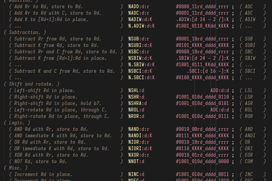
The AVR instruction set does a weird thing with disjoint fields inside instructions, so I added support for that into Torque (see how in the screenshot below, the 6-bit A field has been cleaved in two by the 5-bit r field?).
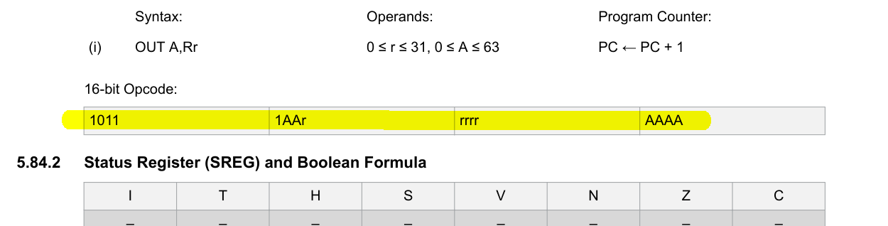
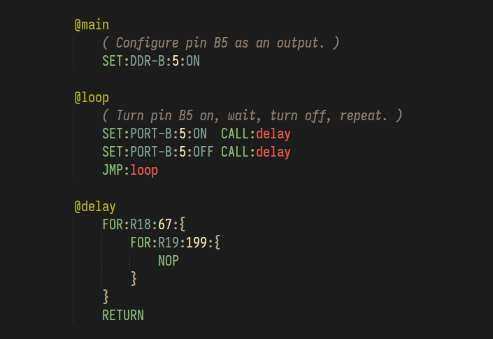
Here’s what the code for blinking an LED looks like. The for loops are really nice to use, they’re just a quick macro that sets up a register as a counter and handles all the decrementing and jumping for you. They’re so much nicer to work with than the old-fashioned do-everything-yourself approach.
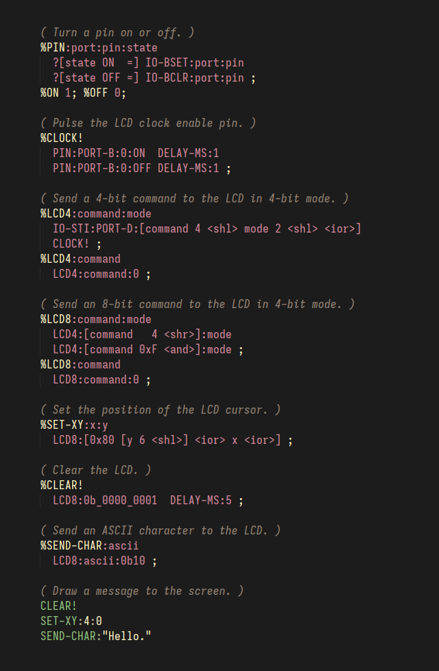
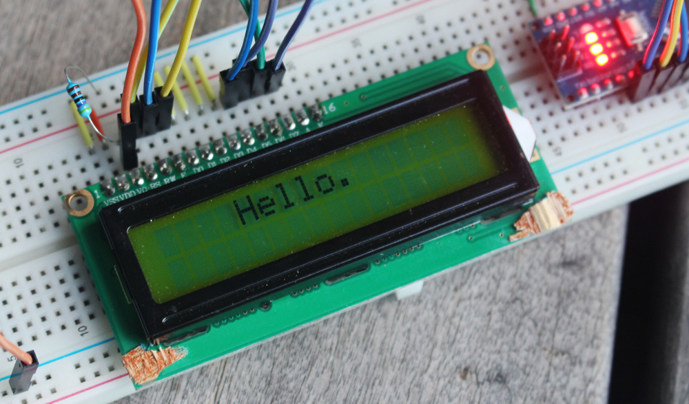
And here’s a screenshot showing how macros can turn low-level code into really nice high-level code. I wrote some code to get the ATmega328 to interface with one of those ubiquitous 16 character wide, 2 line LCD displays. To send a command to the screen, you write the first four bits to four data pins, then pulse the clock pin, and then write the next four bits and pulse the clock pin again. For something like the ‘set cursor position’ command, the X and Y coordinates also have to be packed into the command in a particular way.
With the help of the stack of macro definitions at the top of the screen (in purple), I’m able to write very short declarative code that’s easy to understand (in green):
What’s next?
So far I’ve got a nice workflow going, where I can write code in Torque and beam it over to either microcontroller. Next up, I’ll start designing and implementing a Bedrock system that runs on the ‘328. I’m a bit nervous about this because it’s gonna be a pain to debug, but y’know, there’s nothing to it but to do it.
I’ve got plans for a couple of helper circuits that should aid with debugging when I get around to making them, and I can always poke and prod the circuit with the pins on the Raspberry Pi too, so how hard could it possibly be?
Thanks
Thanks for your unerring support in my work this year, especially through the drought that was the 2026 academic year. I hope you enjoy following along with this action-packed November. See ya next time!