This weekly debrief is for paying supporters of my work. Please only read if you’ve paid. Thanks!
→ Click here if you've paid ←
I’m still working away on the Bedrock hardware projects, slowly stepping my way up towards having a Bedrock system running on a couple of chips. The November Turbothon continues.
Bus terminal
I’ve gotten to the point where I can design the Bedrock system board and start developing the firmware for the ‘328 chip that will control the whole system, but I need a way to easily peer inside the chip to see what the state of the Bedrock system is (so that I can see if the instructions are executing correctly). This is easy enough to solve: I can use the device bus to send the state of the stacks and such out to a custom device that can display it all nicely. This is going to be the debug device, and will be able to be reused for developing other Bedrock hardware systems in the future.
Buuut, how do I now check that the device bus is working correctly? I need to be able to check if the Bedrock system is sending out commands and receiving responses correctly. For this, I need another device, a bus terminal that I can use to tap into a device bus and manually key in commands or receive responses.
How it’ll work
First up, here’s a scrappy render of what it’ll roughly look like. It’s missing some buttons and connectors, but this is the general idea.
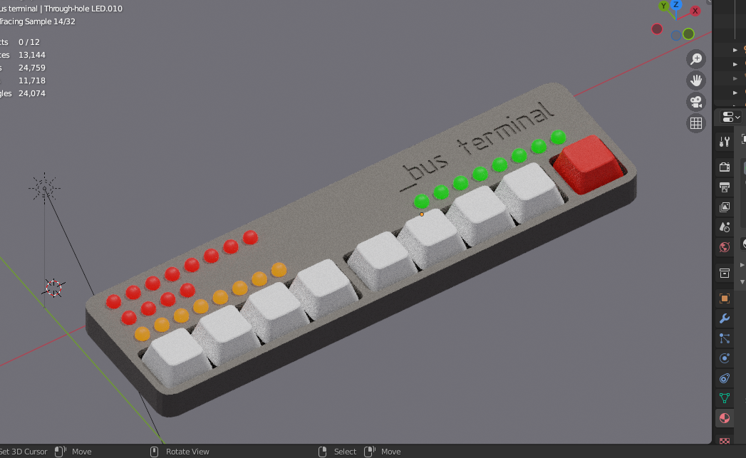
The LEDs on the left-hand side show the command sent by a Bedrock system or by the terminal. The top bank of LEDs displays the device slot and port number addressed by the command (as sent by the LDD and STD Bedrock instructions), the next bank of four red LEDs contains the command ID (whether it’s a read, write, or other sort of command), and the bottom bank of amber LEDs contains the data byte used when writing a byte to a device port. The LEDs on the right-hand side show the response for the current command.
The row of eight white keys is used to key values into each bank. There’ll be a button next to each bank of LEDs, and pressing that button will clear the corresponding bank and make it active, allowing bits to be entered into it. An additional indicator LED on each bank will show which bank is active. The single red key will send the keyed-in command or response out to the bus.
Finally, a mode switch (also missing from the image) will toggle between send, receive, and monitor modes. In send mode, the bus terminal will act as the Bedrock system, taking control of the device bus and sending commands out to devices. Only the left-hand banks will be able to be made active in send mode, and the response bank will light up with the received response from the recipient device. In receive mode, the bus terminal will act as a device connected to the Bedrock system. The left-hand banks will light up with a received command, and the keys will be used to type out and send the response byte. Only the right-hand bank will be active in receive mode. In monitor mode, the bus terminal will act as a passive listener ( a wire tap, I guess), displaying the most recent command and response sent on the wire. I’d also like to add some kind of connector that would allow me to exfiltrate these commands out to a Bedrock stream device, allowing them to be displayed and analysed by a separate Bedrock system.
How I’m gonna make it
The other purpose of this bus terminal thing is that it’s a decently-sized test bed for learning some skills I’ll need for the next stages of the whole project. It’ll be the first ‘polished’ hardware device I’ve made, with a custom printed circuit board and a 3D printed plastic enclosure. I haven’t touched any of that stuff before, so this will be a good way to start.
I want to try to use solely through-hole components for this, just to minimise the complexity and the number of new skills I’ll have to learn to make it. It’d also be nice to be easier for other people to solder up. Just thinking ahead.
I’ll also be making two working bus terminals to start with, because I can use one to test the other. I’ll be able to hook them up together, flick one into send mode and the other into receive mode, and type out commands between them to see if they make it to the other end.
The component list is looking nice and straightforward. This is what I’ve figured out so far:
- ATtiny85 microcontroller
- 18 red LEDs, 11 amber LEDs, 11 green LEDs
- 9 keyboard switches, 4 round buttons, 1 three-pole mode switch, 1 power switch
- 4 serial-in parallel-out latching shift registers (74HC595) for controlling 32 LEDs
- 2 parallel-in serial-out shift registers (74HC165) for reading 16 button/switch inputs
- 9 key caps
- An as-yet-undecided device bus connector, some header pins, a battery pack and voltage regulator, a bunch of resistors.
Those big white and red keys in the render are mechanical keyboard keys, by the way. I want this thing to be nice to use and it turns out that mechanical keyboard switches are more or less a commodity item these days. When I was first looking at parts I accidentally thought that the switches were gonna cost something like NZD$10 or NZD$20 each, but it turns out that they’re often sold in packs of ten. Thank goodness.
Next steps
I’ve planned out how the device will behave, what the interface needs to look like, all of that functional stuff. Next is going to be designing the circuit, the board layout, and the firmware. I’ll need to lock down the parts list real soon so that I can place an order, things always take a bit to reach my corner of the world.
I’m going to use this project as an opportunity to learn SolidWorks too, for the future. I’ve been using Blender to sketch out what the device should look like, but I really need a decent parametric CAD program to make it easier to tweak dimensions and things after the fact and to produce an accurate enclosure model for 3D printing. Blender is wonderful for meshes and rendering and making things look beautiful, but it doesn’t give me the control I need for this kind of thing.
I learned Autodesk Fusion during semester 2 at uni this year for the design course, and, well, I wouldn’t say the experience was painless. The actual parametric modelling functionality and technical drawing stuff is fantastic, but a lot of software offers that, I’d just never been exposed to that sort of workflow before. Unfortunately for Fusion (and me), this wonderful workflow is wrapped up in a frustratingly bad user experience, just the absolute worst time I’ve had with a piece of software since Microchip’s MPLAB IDE. Fusion takes a mortal age to launch, it somehow takes the same amount of time to close down, it’s a laggy mess to use once it’s finally open, and it insists on storing all of your files in ‘the cloud’, which means that they take forever to load and you’re never quite sure where they are.
SolidWorks is probably the most eye-wateringly expensive piece of software I’ve encountered so far (USD$2820 per annum, with a generous 15-day money back guarantee), the only way I’m able to consider using it is through the free student license, but it seems to run well on my laptop and it’ll probably be a good program to know in the future when I’m looking for jobs.
Anyway, yeah, so I’ll also need to learn the ins and outs of 3D printers, and how to start designing a decent plastic case that can be opened and closed without breaking. Plenty of things to keep me busy.
Thanks
That’s a wrap for this week. Thanks for following along and supporting me, it means a lot. Catch you next week!